
Power Reserve and stopwork
Power Reserve and stopwork
POWER RESERVE AND STOPWORK
The power reserve is relatively easy to indicate on a mechanism with a fusee. As the fusee is a mobile part that turns in one direction when the instrument is wound and in the other when it is operating, a hand attached to the fusee or its shaft can serve to indicate the wind of the spring. This is the case for the compteur, where the power reserve and stopwork (which limits how far the spring can be wound to prevent the chain from breaking) are both located at the end of the fusee shaft:
1) The first stopwork wheel (1, Fig. 50) has 12 teeth and is fitted on the square fusee shaft.
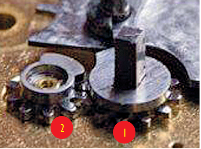
2) The second stopwork wheel (2, Fig. 50) has 8 teeth and gears with the first.
3) A pinion with 12 leaves (3, Fig. 51) is fitted on the square fusee shaft above the first stopwork wheel.
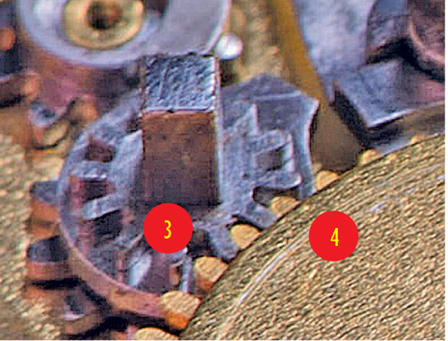
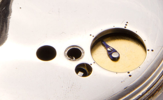
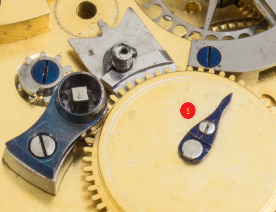
4) This pinion (3) drives a wheel with 60 teeth (4, Fig. 51), which has an index (5, Fig. 52) that indicates the power reserve on the dome, as we will see shortly.
How the stopwork works:
When the user turns the fusee shaft to wind the spring, this simultaneously turns both the second stopwork wheel (2) and the wheel with the index (4) via the first stopwork wheel and the pinion on the shaft.
Obviously, the stopwork wheels limit how far the spring can be wound. In this instance, the maximum amount that the spring can be wound is just under 5 turns.
Furthermore, the wheel with 60 teeth that supports the index will have made just under 1 turn and the index will show that the spring has been fully wound.
When the compteur is running, all of these stopwork and power reserve wheels turn in the opposite direction until the stopwork limits the rate and the index shows that the spring is completely unwound.